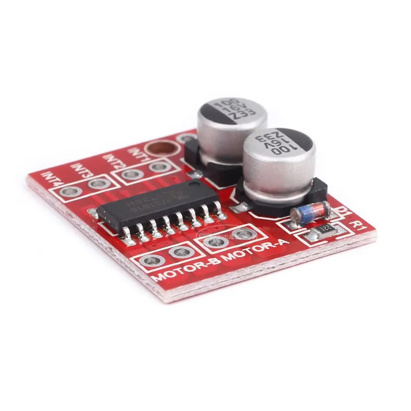
L298N Dual H-Bridge Stepper Motor Driver
5.44RON
- Stock: In Stock
- Model: M011.HBL298N
Your orders placed until 16:30 on weekdays are shipped on the same day.
L298N Dual H Bridge Stepper Motor Driver
The L298N Dual H Bridge Stepper Motor Driver module is an excellent choice for battery-operated smart vehicles, robotic toys, and other automated devices. It offers the ability to control direction, adjust speed via PWM, and drive dual H-bridge stepper motors, outperforming the conventional L298N driver.
Key Features:
- Employs an imported original chip with an integrated low on-resistance MOS switch, ensuring minimal heat production and eliminating the need for a heat sink. This makes it particularly suitable for battery-operated devices.
- Offers dual 1.5A continuous current, with a peak current of up to 2.5A. It also includes a built-in thermal protection circuit that automatically recovers once the temperature decreases.
- Its compact size, lightweight design, and zero standby current make it an excellent choice for model vehicles.
Technical Specifications:
- Capable of driving two DC motors or a 4-wire two-phase stepper motor.
- Module supply voltage ranges from 2V to 10V.
- Signal input voltage ranges from 1.8V to 7V.
- Single operating current is 1.5A, with a peak current of up to 2.5A. Standby current is less than 0.1uA.
- Includes a built-in common conduction circuit to prevent motor malfunction when the input pin is left floating.
- Features a built-in thermal protection circuit with hysteresis effects (TSD) to prevent damage from motor stall.
- Dimensions: 24.7mm x 21mm x 5mm (L x W x H), ultra-compact size.
- Mounting hole diameter: 2mm.
- Weight: 5g.
Usage Guidelines:
- Reversing the polarity of the power supply can cause circuit damage.
- Ground or output short circuits, as well as motor stalls, can trigger the heat protection mechanism. Exceeding a voltage of 10V and a peak current of 2.5A may damage the chip.
- For connections, INx should be linked to the MCU I/O port, while MOTOR-A and MOTOR-B should be connected to the motor.
DC Motor Drive Logic Truth Table:
A functional diagram will be provided for reference.


